
Overview
The POL Series MPO/MTP Polarity Tester verifies fiber sequence and continuity in MPO/MTP patch cords and fan-out assemblies. A visible red-light source and 7-inch color display help operators identify the channel mapping during production, incoming inspection and finished-cable quality control.
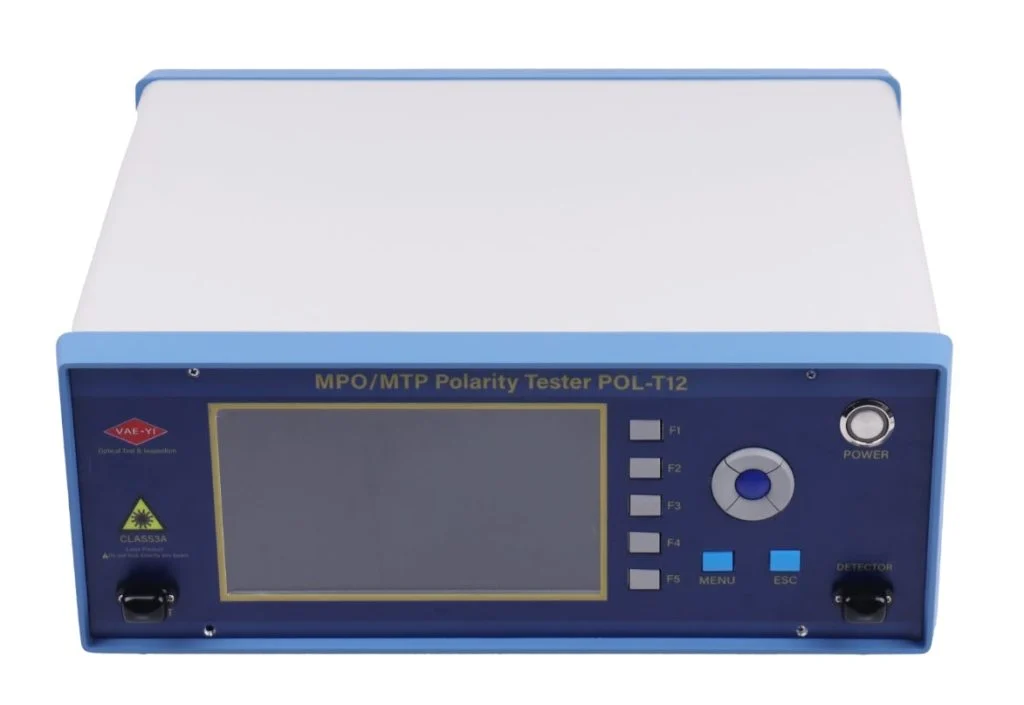
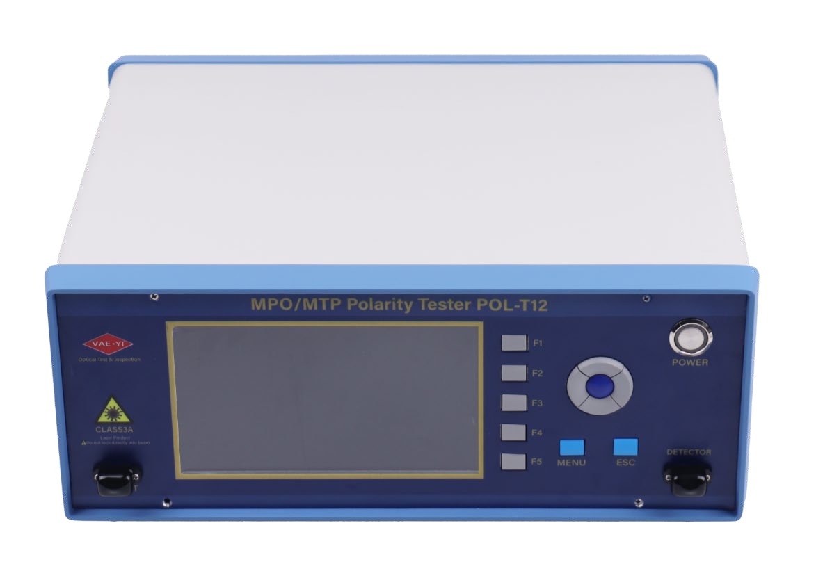
Choose POL-T12 for 12-fiber production or POL-T24 for selectable 12/24-channel testing. The product photograph shows the POL-T12 model.
Key Features
- Two test formats: MPO-to-MPO patch-cord testing and fan-out fiber-sequence verification.
- Fast result display: specified test time below 1 second, with a 7-inch, 800 × 480 color LCD.
- Clear quality-control feedback: green PASS indication or red FAIL indication with abnormal channels highlighted and an audible alarm.
- Custom fiber mapping: learn a reference cable automatically or edit channel assignments manually; saved mappings remain after power-off.
- Single-mode and multimode support: SMF 9/125, MMF 50/125 and MMF 62.5/125.
- Bilingual operation: English and Chinese menus, direction/confirm controls and F1–F5 shortcut keys.
Choose Your Model
Fiber & Connector Compatibility
Both models support SMF 9/125, MMF 50/125 and MMF 62.5/125 fibers. POL-T12 has 12-fiber MPO/PC male optical input and output interfaces; POL-T24 has 24-fiber MPO/PC male interfaces. Match the cable fiber count, connector gender and interface format before ordering. MPO/PC conversion cords and MPO adapters are optional and must be selected for the cable under test.
Technical Specifications
Built-in & Custom Fiber Mappings
Use F2 to create a custom mapping by connecting a known reference patch cord or editing channel numbers manually. Save it under a name different from the built-in presets. Stored custom mappings are retained after power-off.
Testing Workflow
MPO-to-MPO Patch Cords
- Power on and enter the main test screen.
- Press F1 to select the required mapping for the chosen model.
- Connect the two cable ends to OUTPUT and INPUT using the appropriate interface arrangement.
- Read the PASS/FAIL result and check any highlighted abnormal channels.
Fan-out Assemblies
Press F4 and connect the MPO end to OUTPUT. Select all-on mode for a quick continuity check, automatic mode to illuminate channels sequentially, or manual mode to illuminate and identify one channel at a time.
Controls & Connections
The front panel provides the LCD, optical OUTPUT and INPUT, power control, direction/confirm keys, MENU, ESC and F1–F5 shortcuts. ESC returns without saving changed settings. The rear panel provides USB communication, a LOG foot-switch interface, a cooling fan, AC power input and a rear power switch. A foot switch is not listed in the standard package.
Standard Package
Optional Connection Accessories
Typical Applications
- In-process and final inspection of MPO/MTP patch cords and fan-out assemblies.
- Batch incoming inspection of purchased MPO cables.
- Polarity confirmation during high-density data-center MPO cabling acceptance.
- Fiber-sequence validation in connector development and optical-component quality control.
Care & Warranty
The instrument uses visible red light; protect your eyes and avoid looking into optical outputs. Clean MPO test ports regularly with suitable cleaning tools. Switch off and fit dust protection when not in use. Protect the unit from impact and do not disassemble it; arrange professional servicing when required.
The stated warranty is 18 months from delivery, covering faults not caused by misuse. Human-caused damage, external mechanical damage, unauthorized disassembly and transit damage are excluded. Materials and repair service may be charged after the warranty period; confirm terms in the quotation.
For a configuration inquiry, provide the MPO fiber count, fiber type, connector/interface specifications, required polarity mappings and equipment purchase quantity.
LET’S DISCUSS YOUR APPLICATION
Tell Us About Your Testing Requirements.
For this product, share your test setup, required measurements and expected purchase quantity.
Your Test Setup
Fiber type, connector interface, link length and required test functions.
Your Test Requirements
Polarity, continuity, loss or OTDR measurements, as relevant to the selected equipment.
Your Purchase Quantity
Number of tools or equipment units, sample needs or estimated order quantity.
Not sure about every detail? Send the information you have.
Use our contact page for the inquiry template, email and WhatsApp options, or contact us directly below.
Email Our Team