
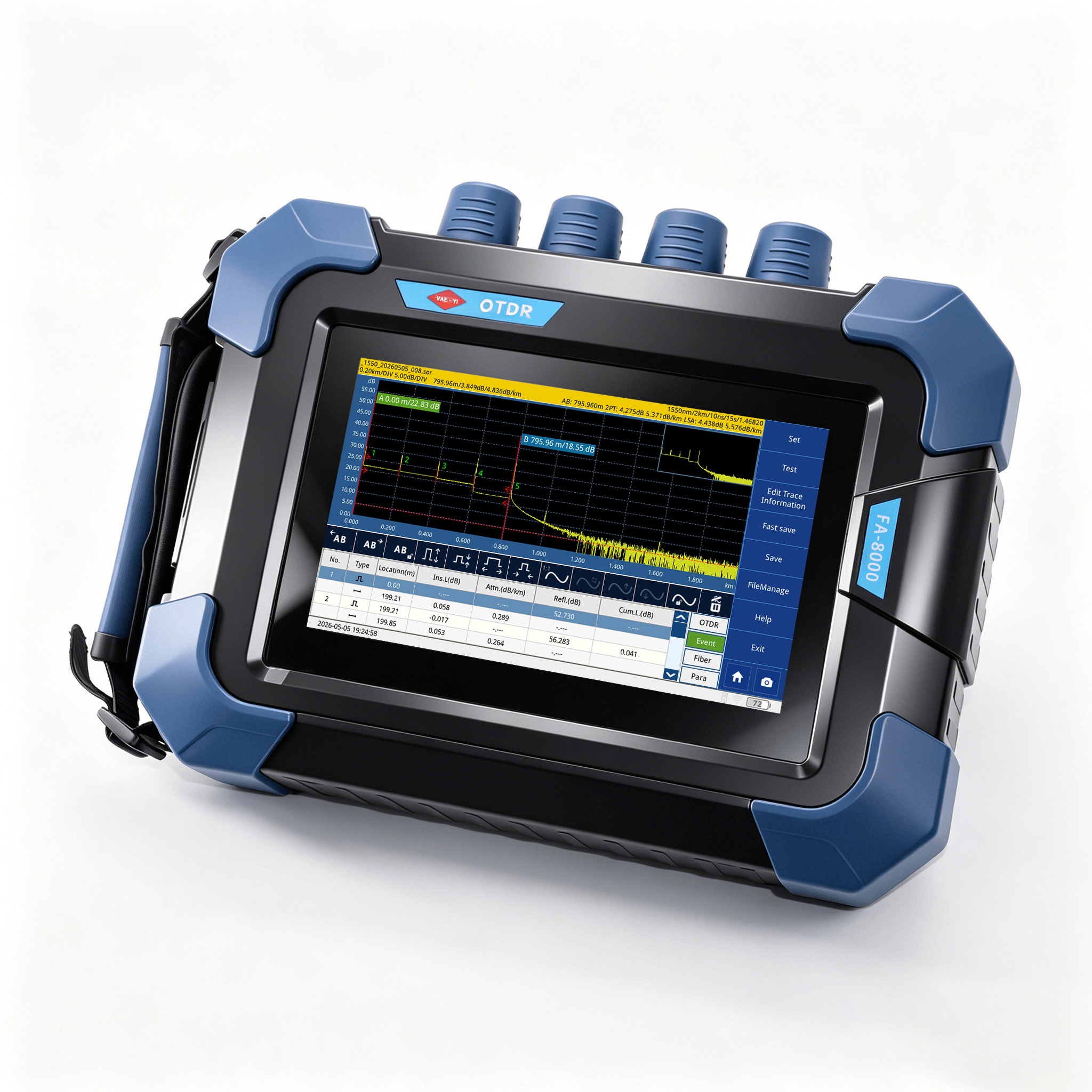
Overview
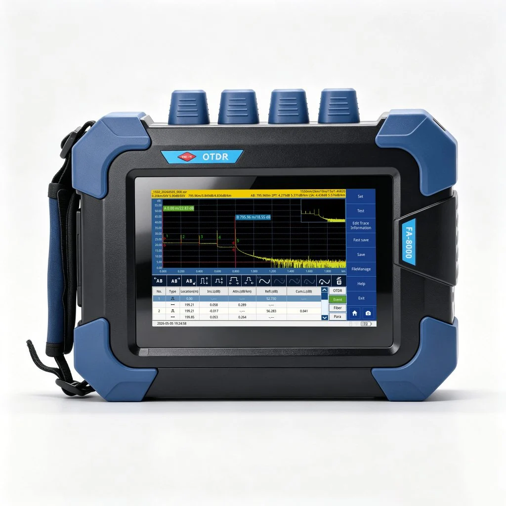
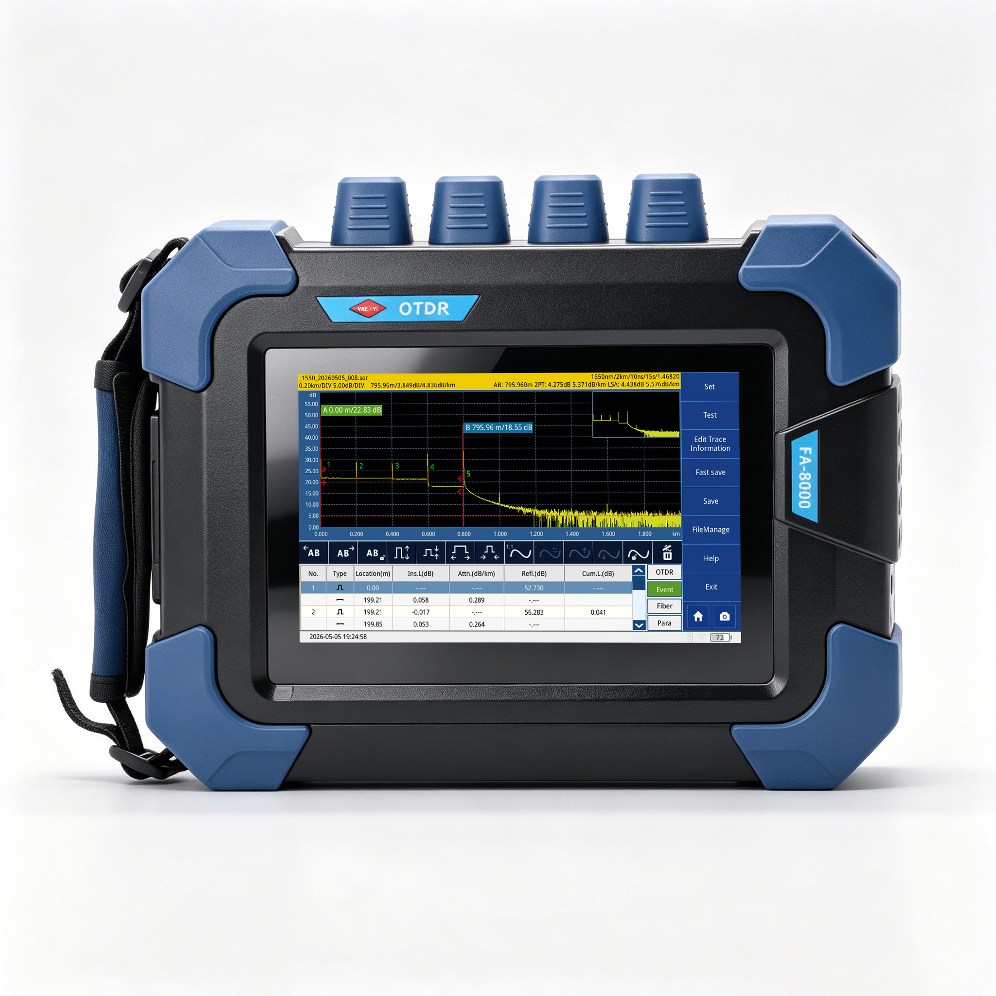
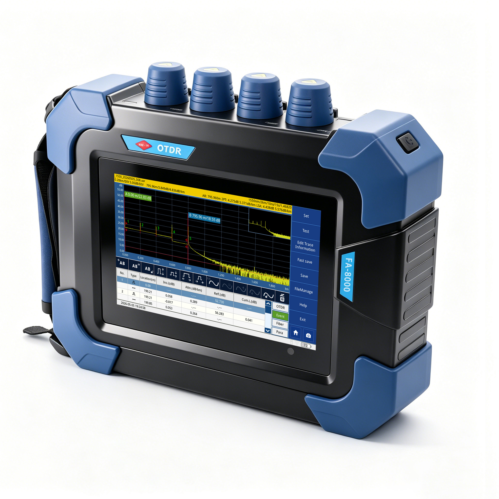
The FA8000 is a PON network line tester for FTTx installation, link evaluation and maintenance troubleshooting. OTDR measurement, graphical link analysis and optical test functions support event identification and fault-location work across fiber networks.
Key Features
- PON / FTTx analysis: a graphical FTTx mode helps identify splitter arrangements and port counts. The supplied material describes support for 1×128 splitters; confirm the selected configuration against actual splitter and link loss.
- In-service diagnostics: a 1625 nm test configuration with filter is specified for online testing. Confirm live-link compatibility and the ordered optical configuration before use.
- Intelligent link view: one-key operation with graphical pass/fail results simplifies routine link assessment.
- Detailed OTDR settings: selectable pulse widths, averaging times and sampling resolution support different test requirements.
- Integrated test functions: visible fault location, 1310/1550 nm optical power measurement and a stable light source complement OTDR work.
- Display and records: a 7-inch touch screen and SD-card trace storage support field review and maintenance documentation.
Technical Specifications
| Parameter | Specification |
|---|---|
| Test wavelengths | 1310/1550 nm; 1625 ± 20 nm |
| 1310/1550 nm dynamic range | 34/32 dB or 44/44 dB, depending on configuration |
| 1625 nm dynamic range | 42 dB with filter installed |
| Pulse widths | 5, 10, 20, 40, 80, 160, 320, 640, 1280, 2560, 5120, 10240, 20480 ns |
| Event dead zone | 1.2 m |
| Attenuation dead zone | 6 m |
| Linearity | ±0.05 dB/dB |
| Loss threshold | 0.05 dB |
| Loss resolution | 0.001 dB |
| Sampling resolution | 0.125–8 m |
| Sampling points | 64K |
| Distance uncertainty | ±(1 m + 2.5 × 10⁻⁵ × distance + sampling interval) |
| Measurement range setting | 0.3–200 km |
| Typical real-time refresh | 1 second |
| Trace storage | SD card, ≥8 GB; over 10,000 traces |
| Measurement durations | 5, 10, 15, 30 seconds; 1, 2, 3 minutes, selectable |
Dynamic range is measured at maximum pulse width with 3-minute averaging. The 1625 nm value is measured with a filter installed. Measurement-range settings are not guaranteed usable distances on every link.
| Parameter | Specification |
|---|---|
| VFL wavelength | 650 nm |
| VFL output power | ≥5 mW |
| VFL maximum test distance | 3 km, as listed in the specification |
| OPM calibration wavelengths | 1310 / 1550 nm |
| OPM measurement range | −40 to 0 dBm |
| OPM measurement accuracy | ±0.02 dB |
| Light source wavelengths | 1310 / 1550 nm; ±20 nm wavelength tolerance as listed |
| Light source output power | −25 to −10 dBm bounds in the specification; customizable |
| Light source modulation | CW / 270 Hz / 1 kHz / 2 kHz |
| Light source interface | Same as OTDR test port |
| Parameter | Specification |
|---|---|
| Viewing area | 0.3 × 0.28 mm |
| Resolution | 0.5 μm |
| Magnification | 400× |
| Signal interface | USB |
| Output format | PAL / NTSC |
| Parameter | Specification |
|---|---|
| Display | 7-inch touch screen; 1024 × 600 resolution |
| Dimensions | 263 × 75 × 203 mm, as listed in the specification |
| Weight | 1.784 kg |
| Operating temperature | −10 to +50°C |
| Storage temperature | −40 to +70°C |
| Relative humidity | 0–95%, non-condensing |
| Power supply / runtime | Lithium battery; continuous working time ≥8 hours stated in the specification |
| Warranty | 18 months; confirm applicable terms with the quotation |
Measurement Conditions
The supplied specification uses standard PC-type connectors and excludes uncertainty caused by fiber refractive index. Dead-zone test conditions are a reflective event within 10 km, 45 dB return loss and minimum pulse width. Actual testing requires appropriate settings for the fiber, connectors, link loss and operating conditions.
Configuration & Package Confirmation
The supplied document describes the functions below but does not provide a standard packing list or accessory quantities. Confirm the supplied items and any optional modules in the quotation.
| No. | Item | Purpose / confirmation |
|---|---|---|
| 1 | FA8000 optical test configuration | Select wavelengths and dynamic range for the required fiber-link tests |
| 2 | 1625 nm filter configuration | Confirm the configuration needed for in-service diagnostics |
| 3 | VFL, OPM and light-source functions | Confirm enabled functions and optical interfaces on the supplied unit |
| 4 | USB end-face inspection | Confirm the required inspection configuration and supplied equipment |
| 5 | SD-card storage | Confirm card inclusion and capacity for trace storage |
Typical Applications
- PON / FTTx installation, link evaluation and fault troubleshooting
- Graphical analysis of splitter-based fiber links within the selected configuration’s capability
- In-service fault diagnosis using the specified 1625 nm configuration
- Optical power checks, visible fault location and connector end-face inspection with the appropriate functions
- Trace recording for routine maintenance and project documentation
For configuration advice, use the inquiry section below to share wavelengths, splitter ratio, approximate link length and loss, live-link testing needs and purchase quantity.
LET’S DISCUSS YOUR APPLICATION
Tell Us About Your Testing Requirements.
For this product, share your test setup, required measurements and expected purchase quantity.
Your Test Setup
Fiber type, connector interface, link length and required test functions.
Your Test Requirements
Polarity, continuity, loss or OTDR measurements, as relevant to the selected equipment.
Your Purchase Quantity
Number of tools or equipment units, sample needs or estimated order quantity.
Not sure about every detail? Send the information you have.
Use our contact page for the inquiry template, email and WhatsApp options, or contact us directly below.
Email Our Team